A significant drawback of many renewable energy sources is their intermittent electricity output, which means they are often seen as unreliable. Solar, wind and tidal power will all need wide scale energy storage in order to provide a smooth supply or quickly respond to changes in consumption. Building the storage infrastructure is critical to expanding renewables’ share of generation and making them competitive on cost.
Hydrogen Fuel Cells
A fuel cell converts the chemical energy from oxidation reactions directly into electricity without the need for high temperature combustion. Proton Exchange Membrane (PEM) fuel cells are the most popular and well tested type of fuel cell. They have been developed for applications in electric vehicles, portable power supplies and even for use on spacecraft. In times of low demand, surplus energy from renewables can power electrolysis, a process in which electric current passes through an aqueous solution to split water into hydrogen and oxygen. Hydrogen is a versatile energy carrier that can either be burned in an engine or used in a fuel cell to produce electricity directly [1] – [3].
Commonly, hydrogen is stored in high pressure tanks at up to 60 kPa. Other methods of storage involve reactions with metals to form metal hydrides or a reaction with Nitrogen to form liquid ammonia. Storing hydrogen in a liquid or solid state results in a much higher density and reduces the risk of explosions. However, this also tends to be more complex and expensive, whereas high pressure storage is known to be reliable. In addition, because the gaseous storage involves pure hydrogen, there are fewer energy conversions in which losses can occur. For stationary applications, weight and volume aren’t major limiting factors as is the case with hydrogen powered vehicles [5], [6].
There are several types of fuel cells each requiring different fuels and materials, but the basic principle remains the same. Every fuel cell has three basic components: an anode, an electrolyte membrane and a cathode. Here we are focusing on the PEM fuel cell. Both electrodes are treated with a metal catalyst, most commonly in the form or Platinum or Palladium nanoparticles. Hydrogen gas under pressure comes into contact with the catalyst on the anode’s surface, where each diatomic H2 molecule is decomposed into two protons and two electrons. Protons are able to pass through the polymer membrane towards the cathode but it is impermeable to electrons, which are forced to travel through the external circuit, doing useful work in the process. At the cathode, oxygen from the air is split into separate oxygen atoms that react with the incoming protons and electrons to form water as the only waste product [1] – [3].

A commonly used material for the membrane is Nafion, a polymer made from tetrafluoroethene (used to make Teflon) as well as sulfonic acid, whose SO3H groups allow protons to travel through the material by hopping from one acid group to another [7]. A single cell on its own produces a small voltage, so they are usually combined in large stacks. The number of cells determines the maximum voltage output.
PEM fuel cells offer a number of advantages as a way to store energy. They have high efficiencies in the range of 55-60% in addition to quiet, reliable operation as there are no moving parts. Recovering waste heat from the cell stack in a cogeneration scheme could even increase the efficiency to around 80%. Hydrogen has a volumetric energy content of 8 MJ/litre, or about one quarter of the value for petrol. On the other hand, its energy density per unit mass of 120 MJ/kg is almost three times that of petrol (44 MJ/kg) [7]. These figures may pose problems if we are trying to power vehicles, but stationary energy storage systems are not greatly hindered. Furthermore, a PEM fuel cell can work in reverse to electrolyse water in the first place, so no additional hardware is needed. Only 2% of all hydrogen is produced through electrolysis with the remaining 98% made from natural gas. Fuel cells combined with solar and wind can therefore expand hydrogen into a renewable carrier of energy. It may also prove to be cheaper than natural gas in the long term as the International Energy Agency (IEA) predicts that by 2040, hydrogen from wind power will cost €0.032 per kWh compared to €0.041 per kWh for natural gas [8].
Pumped Storage Hydroelectricity
Pumped storage hydroelectric power is the most common form of energy storage today, making up 97% of the world’s total storage capacity. It is a proven technology dating back over a century. The principle is simple – it relies on two or more dams at different heights above sea level. At off peak demand on the grid, surplus electricity can be used to pump water to the highest reservoir. When energy is required the water from the top dam is released to power generator turbines. A cascade scheme can consist of more than two reservoirs at different heights. Pumping water up a mountain increases its gravitational potential energy, which is a very efficient way to store energy for long periods of time since the losses are practically negligible as long as there are no leaks. Most of the energy loss is due to heat dissipation by the pumps [9].
The amount of energy stored is given by  , where m is the water mass, g is gravitational acceleration (9.81 ms-2) and
 is the vertical height difference between the water intake and turbine, also known as the ‘head’. If we are interested in the power, this depends on the flow rate as well, which can be expressed as a mass or volume flow rate.

Figure 2 above shows the Belmeken Dam in the Rila Mountains, Bulgaria. It is the top reservoir of a cascade pumped storage scheme made up of four Hydro Power Plants: Chaira (864 MW), Belmeken (375 MW), Sestrimo (240 MW) and Momina Klisura (120 MW). The mountainous terrain allows for a reservoir with a volume of 140 million cubic metres at 1900 metres above sea level. There is also a total head of 1550 metres between the top and bottom dams – one of the largest in Europe. All 4 reservoirs combined provide on average just over 1000 GWh per year of clean, renewable energy [10]. Hydro power is very limited by geography, but it is one of the most effective ways to combine generation with storage. Interestingly, Brazil gets more than half of its electricity from it, while Norway gets over 90% of its electricity from hydro power.
Flywheels
A flywheel is a mechanical device designed to store kinetic energy through its angular momentum when rotating at high speeds. Accelerating the flywheel adds energy to the system, which is maintained until it is used or friction forces dissipate the energy. Most large flywheel systems have the rotor supported by magnetic bearings in a vacuum enclosure to minimise friction, extending the rundown time. For a solid cylindrical rotor, the energy stored is given by:
Where: is the wheel’s moment of inertia,
is the angular velocity,
is the mass and
is the radius [11].
The moment of inertia quantifies the resistance of an object to changes in its angular velocity and it varies for different shapes of flywheels. In general this is represented as , where k is like a constant of proportionality. For example, a solid sphere has a k = 2/5, while for a spherical shell k = 2/3. Flywheels are built such that the rotational speed is as high as possible because energy increases with the square of this speed, whereas it only increases linearly with mass. Another consideration is that if the wheel is too heavy it can be torn apart by centrifugal forces at high speed. A bit counterintuitively this means that the tensile strength of the material is more important than its density [12].
Renewable energy sources tend to cause fluctuations in the frequencies of the national grid. For example, if there is a sudden surge of demand on a wind farm that is not generating enough power to meet it, the grid frequency decreases slightly. Too many variations from the standard 50 Hz can damage some devices. Onsite flywheel systems at solar and wind power plants can smooth out these transitions, in effect acting like giant ‘mechanical capacitors’. Similarly, they can be effective at preventing ‘voltage sag’ – a drop in the peak to peak voltage due to unbalanced loads where one load absorbs a large amount of power in a short time.
It has been found that composite materials such as Carbon-fibre reinforced polymers and Glass-fibre reinforced polymers are best suited to withstand the high speeds in flywheels, therefore giving the optimal energy density. Their reliability has been showcased at the University of Texas at Austin where composite flywheels have been tested to 48 000 RPM with more than 90 000 cycles of charging and discharging.
Flywheels can last for a very large number of charging and discharging cycles without any degradation in their storage capacity, unlike with batteries. They have high cyclic efficiencies of around 90% as mainly the generator’s resistance dissipates some energy. It is also easy to monitor the amount of energy left in a system by measuring the rotational speed. The response times of flywheels for either putting energy in or taking it out are much faster compared to other storage methods, which makes them suitable for applications where sudden surges of power are required. As an example of this, during a power cut, hospitals may use flywheels for up to a few minutes to ensure uninterrupted power until back-up generators are brought online. The same applies to data centres where a smooth transition to emergency power is important [12].
Another interesting application is in regenerative braking systems in cars where some of the car’s momentum is transferred to the flywheel while braking. It temporarily stores kinetic energy after which it can be released during acceleration at the press of a button. Ultimately this makes cars more fuel efficient since less energy is wasted as heat through the brakes. The Kinetic Energy Recovery System (KERS) in Formula One worked in this way up to the 2013 season after which the technical regulations of the sport changed. It could provide an additional 81 horsepower (the same as a small hatchback) for 6.67 seconds per lap at the press of a button [11].
On the International Space Station and on many satellites in orbit, solar power is the primary power source. As the space station is frequently in darkness on each orbit, it relies on chemical batteries that are charged when the station is in direct sunlight. These batteries power vital life support equipment and other instruments, but need to be replaced every 6-7 years due to degradation. Initially, nickel-hydrogen batteries were used, but more recently these were replaced with lithium-ion batteries which offer higher energy densities. Flywheel energy storage has been suggested as a more long term solution because of its reliability and long service life – both important when it comes to life support in space. It could be used in combination with batteries to reduce the mass that needs to be launched by about 35%, not just for the space station but also for satellites. A proposed system for NASA and the ISS will have a composite flywheel that can store more than 15 MJ of energy at over 93% round trip efficiency. The maximum power for one unit will be 4.1 kW [12].
Superconductor Coils
A more ambitious form of storing energy is the use of superconductor coils to store large electric currents. Superconducting materials have no electrical resistivity, therefore no energy is dissipated as heat when a current passes through them. This effect was first observed in 1911 by Heike Onnes when Mercury was cooled to 4 degrees Kelvin. Since then many other materials have been found to become superconducting below a certain critical temperature – for example Tantalum at 4.47 K and lead at 7.2 K. Up until 1986, the highest known critical temperature of 23 K was believed to be near the theoretical upper temperature limit. However, to the surprise of many, certain ceramic materials were found to exhibit superconductivity at higher temperatures, hence they were classed as ‘high temperature superconductors’. A Lanthanum-Copper-Barium ceramic that became superconductive at 30 K was the first of these [13], [14]. The table below shows other examples.
| Material | Critical Temperature (TC) |
| Yttrium-Barium-Copper-Oxide | 92 K |
| Bismuth-Strontium-Copper-Oxides | 110 K |
| Thallium-Barium-Copper-Oxide | 125 K |
Pure metal superconductors are referred to as Type I while alloys or ceramics are known as Type II. A severe disadvantage of regular superconductors is that a lot of energy is required for cryogenics systems to cool the material, therefore the benefits derived from no transmission losses are cancelled out and even reversed. However, there’s interest in high temperature superconductors as they can be easily cooled by liquid Nitrogen, which forms at 77 K and costs as little as milk. It is difficult to draw out ceramics into wires for coils and some energy is still needed to cool the Nitrogen [13], [14]. So, potentially for an energy storing coil to be economical, it would need to save more energy over time than it consumes.
The energy in a superconducting coil can be found using the formula where L is the coil inductance in Henries and I is the current in Amperes.
Battery Storage
The most widespread technology for household battery banks are the lithium-ion and lithium-polymer batteries. A well-known example is the Tesla Powerwall which offers a capacity of 13.5 kWh for a cost of £6,350 and is able to provide about 4 kW of continuous power. A battery pack for the Tesla Model 3 has a practical capacity of 40 kWh [15].

Installations of solar power in homes and workplaces are steadily becoming more popular in the UK, with their generating capacity increasing from 2.8 GW in 2013 to over 5 GW in 2015. As a result, the market for home battery systems will likely see increasing demand as well as more competition. In 2018 there were about 700 000 new solar installations and currently 1.5 million houses use photovoltaic panels. Slightly unexpectedly, the UK is one of the European countries with the fastest growth in domestic solar power [16]. This may be due to the incentive provided by the Smart Export Guarantee (SEG) scheme that ensures small renewable producers get paid for exporting excess power to the National Grid. Previously this was called a Feed-In Tariff. The UK’s mild temperatures also help preserve PV cells for longer as high temperatures can degrade them quickly. After an initial investment of about £6,000 to £10,000 the installation can begin paying itself off and eventually generate income after the ‘pay-back’ period. Moreover, in some cases the government offers interest free loans for installing PV panels. Such systems are not practical without reliable battery banks.
How does a Lithium-Ion battery work?
Firstly, we need to understand the concept of the electrochemical series of metals. It lists metals in order of their tendency to be either oxidised (lose electrons) or reduced (gain electrons). This tendency is represented by voltage values called standard electrode potentials. The more positive the value is, the more easily a metal atom loses electrons. Conversely, large negative voltages indicate a metal that is susceptible to reduction and therefore the sign is different to account for the electrons movement being in the other direction. Amongst metals that can practically be used in batteries, Lithium has the highest electrode potential of +3.04 V as it has a single outer shell electron [17].
Structure
There are actually some similarities with the structure of the hydrogen fuel cell, but different chemical reactions are taking place. A Lithium-ion cell consists of a metal oxide cathode, an anode made from graphite and an electrolyte solution between the electrodes. There is also a separator layer that makes sure there cannot be a short circuit between the electrodes inside the cell in case the electrolyte evaporates due to high temperatures. At the anode the conventional current goes into the cell, so it flows out of the cathode. This is not to be confused with the flow of electrons which is in the opposite direction – from the anode to the cathode. The purpose of the electrolyte is to only allow positively charge Lithium ions to pass while blocking electrons.
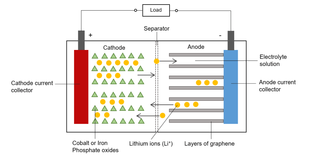
Materials for the cathode commonly include Lithium Cobalt oxide (with a layered structure) and Lithium Iron phosphate. The formation of this oxide involves transfer of electrons in ionic bonding. A battery essentially exploits this by providing a separate pathway for electrons in the formation of the oxide. Since the reactions involved are reversible, recharging is possible as the direction on this pathway can change [17], [18].
What happens in a charge-discharge cycle?
When a power source is attached to the electrodes, electrons flow away from the cathode towards the anode. At the same time, lithium atoms are ionised and attracted to the anode as a result of the electric field formed in the cell. Electrons and Lithium ions recombine in the layers of graphene sheets at the anode, where they are stored. This is an unstable, energetic arrangement, much like having boulder precariously perched at the top of a peak. This electrochemical potential is what stores the energy. The Lithium atoms want to get rid of their outer electron and return to the stable oxide state (such as Lithium Cobalt oxide).
Upon connecting a load across the cell, the electrons in the anode are free to flow around the external circuit, while Lithium is ionised again and travels through the electrolyte back to the metal oxide. The electrons release the chemical potential energy as they pass through the load. At the cathode, Lithium ions and the electrons recombine again to reform the oxide. The whole cycle repeats when a power source recharges the battery again.
At the cathode:
At the anode:
Full reversible reaction:
An important process that happens on the first charge with all Li-ion batteries is the formation of a so called Solid Electrolyte Interface (SEI) layer. As Lithium ions pass through the electrolyte they are coated with solvent molecules. The coated ions then react with graphite to form a solid layer that stops electrons from gradually depleting the electrolyte. Only about 5% of the Lithium is used up by the SEI layer.
Typically, in commercial Li-ion cells, the graphite is coated onto a copper foil whereas the Lithium oxide is coated onto an aluminium foil. These foils act as the current collectors which are connected to the positive and negative battery terminals. All the layers in a cell are then rolled into a cylinder around a central steel core to maximise the surface area for interaction.
Tesla battery packs are made up of small cylindrical cells providing 3 – 4.2 V each. They are combined in modules where the cells are connected in both series and parallel configurations to get suitable voltages depending on the use. Groups of cells connected in parallel means that if some cells are damaged they do not affect the rest of the module. A battery pack for a car like the Model S is made up of 16 modules with a total of 2170 cells. One innovative feature the packs is their battery management system (BMS) that looks after the temperature, voltage protection, amount of charge and detection of individual cell malfunctions. Voltage protection involves cell balancing – a way to ensure each cell is evenly charged or discharged without extremes of voltages. To prevent rapid degradation due to overheating, a cooling system using circulating glycol is used. The cooling channels are in direct contact with the cells. All of these features help the Powerwall achieve a round trip efficiency of 90% as well as a minimum life of 10 years. The Model 3’s battery pack is estimated to last for about 1500 charge-discharge cycles [17].
A lot of research indicates that it may be possible to significantly increase the energy density of lithium-ion batteries by replacing the graphite at the anode with silicon – a material well known in the electronics industry. The difference is that with graphite the ratio of Carbon to Lithium ions is 6:1, but Silicon reacts with Lithium ions to form Li15Si4 (3.75:1 ratio in favour of Lithium) [18], [19]. Therefore, smaller amounts of the anode material can store more Lithium ions, increasing overall capacity.
The difficulty that has puzzled researchers is that the Silicon expands a lot when it reacts with Lithium and shrinks on discharge (although the mass stays the same). Continuous expansion and contraction can disintegrate the anode as well as depleting the electrolyte. One way manufacturers are working around this is to use particles of silicon and silicon dioxide (mostly what sand is made of) that are coated with the regular graphite. Elon Musk has revealed that Tesla also uses this technique. Alongside this, there is some promise in making better anodes with higher silicon concentrations such as the one produced by a company called Sila Nanotechnologies in the US. Their solution is to place silicon within a porous scaffolding material so that there is room for safe expansion without contact with any other parts of the cell. This might eventually increase capacity by 40% and allow for very fast charging. Another company, Enovix Corp. is taking photolithography techniques from semiconductor manufacturing to produce a porous, lower density silicon layer that tolerates expansion by filling its internal gaps instead of growing outwards [18], [19].
Supercapacitors
Supercapacitors (also called ultra-capacitors) store orders of magnitude more energy compared to normal capacitors and come close to battery storage in terms of energy density. Their capacitances can typically range from 100 – 3000 Farads, while regular capacitors are in the nano (10-9) and micro (10-6) Farad range. Supercapacitors share some similarity with batteries in that they make use of electrochemical effects, but there are no reduction-oxidation reactions.
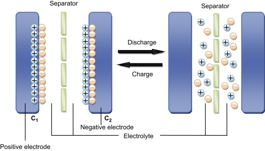
Regular capacitors are made up of two conductive metal plates separated by an insulator called the dielectric. During charging, electrons accumulate on one plate which repels the electrons on the opposite side. This leaves one side with a negative charge while the other gets positively charged. An electric field is formed and the charges are stored on the plates until a load is connected across the capacitor to discharge it. The capacitance increases linearly with the surface area of the plates and is also inversely proportional to the distance between them.
In supercapacitors there are also two plates but they are covered in a porous material like activated charcoal in order to maximise their surface area. The plates are immersed in an ionic electrolyte solution and separated by a very thin insulator layer. When the supercapacitor is being charged, ions on each side of the separator form two layers, with the layer next to the plate being of opposite charge. So for example, the negative plate will attract positive ions while pushing the negative ions to the surface of the separator. This is referred to as an electric double-layer and is effectively like having two normal capacitors within the electrolyte as there are two pairs of oppositely charged layers. These layers have a tiny thickness, usually down to the scale of a few molecules across. Because of this, the term electrochemical double layer capacitors (EDLCs) is also used [20], [21].
Some applications
Similarly to flywheels, supercapacitors are able to charge and discharge quickly for a large number of cycles without any degradation. However, they can only supply power for a relatively short time. One area in which supercapacitors may become immensely useful is electric vehicles to supplement battery packs. While a battery pack provides continuous power, supercapacitors can be part of a regenerative braking system which often delivers sudden electrical surges during braking.
Frequent large current drains from batteries are damaging. A combination with supercapacitors that provide instant high current when needed can keep the discharge smooth and extend battery life. After discharge the battery recharges the capacitor for the next peak. For example this is useful in alarms, RFID, GPS trackers and medical equipment. Grid power buffers are another area that might benefit from supercapacitors as they can act as an interface between the load and power plant that smooths out fluctuations in voltage.
Energy harvesting for low power devices such as smart watches, remote sensors or weather station data loggers can be done through supercapacitors. For example, the source may be a PV cell, heat or even walking motion converted to electricity. Any device with an application specific integrated circuit (ASIC) tends to have modest energy requirements, making them ideal to combine with these capacitors.
Final thoughts
The choice of a practical energy storage method depends largely on the energy and power densities. For example, a supercapacitor has a very high power density as it can deliver a lot of energy quickly from a small mass, but it stores less energy per unit mass compared to batteries. So it wouldn’t be the best choice for heating a house. Fuel cells have a high storage capacity but cannot deliver this energy as quickly as flywheels or hydroelectricity, therefore they couldn’t be used in machinery with sudden large power peaks such as cranes. Often a combination of two methods could be the best solution. As an example, a photovoltaics plant may need to buffer energy in flywheels before electrolysing water to make hydrogen.
An area that may see growth in the future is distributed electricity generation where multiple small scale energy sources (such as photovoltaics) are spread out amongst houses, businesses or public buildings. This local group of sources connected with consumers is known as a microgrid. It can be connected to the wide area synchronous grids (national grids) but it can also function independently. Since the electricity sources tend to be close to end users, there is very little transmission loss. Moreover, many microgrids serving different areas will add redundancy in the case of power outages, making the whole grid more resilient. The deployment of smart meters is making it easier to connect domestic generating or storage set-ups to the grid. Outflow and inflow of electricity can even be monitored on an indoor screen. Potentially these meters together with feed in tariffs may provide incentive for more renewable distributed sources.
References
[1] D. Ruzic, Fuel Cells and Hydrogen Economy. 2020. Available: https://www.youtube.com/watch?v=peoO8-_o6NM [Accessed: 15- May- 2020].
[2] “Fuel Cells | Hydrogenics”, Hydrogenics.com, 2020. [Online]. Available: https://www.hydrogenics.com/technology-resources/hydrogen-technology/fuel-cells/. [Accessed: 10- May- 2020].
[3] J.M.K.C. Donev et al. (2020). Energy Education – Fuel cell [Online]. Available: https://energyeducation.ca/encyclopedia/Fuel_cell. [Accessed: June 6, 2020].
[4] “Unlocking the Potential of Hydrogen Energy Storage — Fuel Cell & Hydrogen Energy Association”, Fuel Cell & Hydrogen Energy Association, 2020. [Online]. Available: http://www.fchea.org/in-transition/2019/7/22/unlocking-the-potential-of-hydrogen-energy-storage. [Accessed: 10- May- 2020].
[5] “Hydrogen Storage”, Energy.gov, 2020. [Online]. Available: https://www.energy.gov/eere/fuelcells/hydrogen-storage. [Accessed: 18- May- 2020].
[6] Power-technology.com, 2020. [Online]. Available: https://www.power-technology.com/wp-content/uploads/sites/7/2019/10/Hydrogen_Infographic-1.pdf. [Accessed: 06- Jun- 2020].
[7] “PEM Fuel Cells”, sigmaaldrich.com, 2020. [Online]. Available: https://www.sigmaaldrich.com/materials-science/renewable-alternative-energy/pem-fuel-cells.html. [Accessed: 15- May- 2020].
[8] “Cost of wind-generated hydrogen to fall below natural gas”, Windpowermonthly.com, 2020. [Online]. Available: https://www.windpowermonthly.com/article/1462904/cost-wind-generated-hydrogen-fall-below-natural-gas. [Accessed: 31- May- 2020].
[9] J.M.K.C. Donev et al. (2018). Energy Education – Hydroelectric facility [Online]. Available: https://energyeducation.ca/encyclopedia/Hydroelectric_facility. [Accessed: June 6, 2020].
[10] “НЕК ЕАД – предприятие „Язовири и каскади“”, dams.nek.bg, 2020. [Online]. Available: https://dams.nek.bg/Default.aspx?item=381eb6bd-f2a8-4dfd-b4ba-b892c572a350. [Accessed: 31- May- 2020].
[11] “Flywheel – Energy Education”, Energyeducation.ca, 2020. [Online]. Available: https://energyeducation.ca/encyclopedia/Flywheel. [Accessed: 11- May- 2020].
[12] Openaccess.city.ac.uk, 2020. [Online]. Available: https://openaccess.city.ac.uk/id/eprint/17719/1/AmiryarandPullenA%20Review%20of%20Flywheel%20Energy%20Storage%20System_applsci-07-00286.pdf. [Accessed: 18- May- 2020].
[13] “Superconductivity”, Hyperphysics.phy-astr.gsu.edu, 2020. [Online]. Available: http://hyperphysics.phy-astr.gsu.edu/hbase/Solids/scond.html#c1. [Accessed: 31- May- 2020].
[14] “Superconductors”, Superconductors.org, 2020. [Online]. Available: http://www.superconductors.org/. [Accessed: 24- May- 2020].
[15] “Powerwall | The Tesla Home Battery”, tesla.com, 2020. [Online]. Available: https://www.tesla.com/en_GB/powerwall. [Accessed: 06- Jun- 2020].
[16] “Solar Panels in the UK – How Popular are They? | GreenMatch”, Greenmatch.co.uk, 2020. [Online]. Available: https://www.greenmatch.co.uk/blog/2015/08/how-popular-are-solar-panels-in-the-uk. [Accessed: 31- May- 2020].
[17] Lithium-ion battery, How does it work?. 2020. Available: https://www.youtube.com/watch?v=VxMM4g2Sk8U. [Accessed: 20- May- 2020].
[18] “How to Build a Safer, More Energy-Dense Lithium-ion Battery”, IEEE Spectrum: Technology, Engineering, and Science News, 2020. [Online]. Available: https://spectrum.ieee.org/semiconductors/design/how-to-build-a-safer-more-energydense-lithiumion-battery. [Accessed: 27- May- 2020].
[19] D. Schneider, “To Boost Lithium-Ion Battery Capacity by up to 70%, Add Silicon”, ieee.org, 2019. [Online]. Available: https://spectrum.ieee.org/energy/renewables/to-boost-lithiumion-battery-capacity-by-up-to-70-add-silicon. [Accessed: 30- May- 2020].
[20] “Electrochemical Double Layer Capacitors (Supercapacitors)”, Large.stanford.edu, 2020. [Online]. Available: http://large.stanford.edu/courses/2012/ph240/aslani1/. [Accessed: 30- May- 2020].
[21] “Graphene Supercapacitors: Introduction and News | Graphene-Info”, Graphene-info.com, 2020. [Online]. Available: https://www.graphene-info.com/graphene-supercapacitors. [Accessed: 26- May- 2020].
